|
Back to Vectrex Programming Tutorial Index Dot Drawing Now let us move to something even less complicated, drawing a single dot on the screen. As you might have guessed there are functions for dot drawing provided by the BIOS. These functions are:
Look at Appendix A for more information on each of the functions. Let us first plot a single dot at the center of the screen. To achieve that, we might just simply modify the above program. Instead of printing a text, we could just call Dot_here ($F2C5). One might expect the program to work just fine, but there is a catch to it. Here a screenshot:
The above program looks correct, and it should really work allright, bad sadly it doesn't. There is a catch to the 'Wait_Recal' function. The last thing it does is position the vector beam to -128, -128 at full vector speed. Than it resets the vector position to zero. That positioning to zero does take some time, I don't know exactly how long, but about 20-50 cycles or so. The intensity function is not all that long, so not enough cycles have passed when 'Dot_here' is called. If you assemble the program as it is above you can watch some electronical RC laws. Vectrex plots the end of an uncharging of capacitors on the screen, an e-function, moving from the lower left to the center! Actually you don't need to be concerned by this. I don't think in a real program a drawing directly after calling the 'Wait_Recal' (or the 'Reset0Ref' function, which does also reset the vector beam position to 0,0), ever occurs in any timecritical way. So ususally you don't need to be concerned about timing after resetting. In this really special case we need to insert a delay in order to only produce a dot, and not an e-function. Please modify the above source after the "; special attention here!!!" line with a call to a delay function. The line should be like:
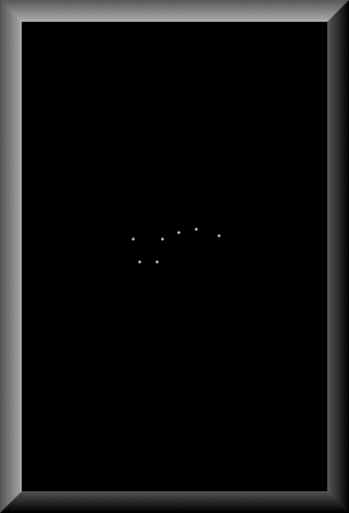
Dot intensities can be varied by two ways (as mentioned somewhere above). First using the, by now known, intensity of vectors and secondly using a BIOS RAM variable Vec_Dot_Dwell ($C828), which is a counter of a loop, for how long the vector beam will be placed on the dot with the current intensity. (WARNING! high intensity and long Vec_Dot_Dwell might result in a burn in on your vectrex monitor, be carefull while experimenting with this!) Now let us move on to something more interesting (?), let us plot a whole series of dots :-). Here a screenshot:
There is not really much to say about the above program. We use a new function called Dot_List ($F2D5), which expects as a parameter the address of a list of dots in the X register. The list consists of pairs of coordinates. These coordinates are each relative to the last position, and as usual the Y coodinate is first, X second. The number of dots to draw is specified in a BIOS RAM location Vec_Misc_Count ($C823). The value you load to that location must be one less than the number of dots you want to plot.
|
|
| Back to Programming Docs Index | |


